Share post
Have you ever had something that partially stopped working, but the thing that stopped working was super useful? That’s what happened with a certain bit of navigation equipment we own. Namely our compass. Not the compass itself, though, that was pretty robust and still working. However, the lamp that enabled it to be seen in the dark was not working, and that can be a big problem.
Sure we have GPS, but GPS has a big problem, namely that it doesn’t know which direction things are pointed in, just where they are going, but that has to be calculated by looking at the straight line of two points, and that can be a delayed calculation, or something that goes horribly wrong in the event you lose signal or you have dangers that are close to you. Needless to say, compasses are great tools.
When replacing isn’t really a good option
I know that many would just jump to replacing the compass. After all, many would first think about a typical camping and hiking compass which can be bought for a small amount of money. But no, everything in the world of marine equipment comes with a special tax that somehow adds a zero or two to the price.
For example, here’s an example compass which is found on what seems like a typical marine supply site: https://nvnmarine.com/products/21466-ritchie-s-53-explorer-compass-surface-mount ($77.19 USD and on sale!).
The compass itself wasn’t the problem, so I figured: why spend money to replace the whole thing when I could instead replace the lighting part?
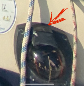
How to approach integrating new stuff into old stuff?
Generally there are some pre-requisites whenever working on fixing things, whether electronic or not:
- You can disassemble and reassemble the device.
- You know how the thing you’re replacing works.
- You know roughly what you want to achieve.
Disassembling
Following this, it was pretty easy to disassemble the light housing, so that took care of step 1. It’s not always easy though, so if you are not used to DIY-ing stuff, it’s a good idea to take a generous amount of pictures and notes if you don’t have a manual to know exactly how things need to go back if needed. Sometimes your first ideas don’t pan out and you need to target a different area to adjust or fiddle with. If you can’t reliably put things back where they were this can be a frustrating experience (which I definitely can say I’ve lived several times).
How it used to work

The above image is what I got when I took off the lighting housing. From this image it was clear to me at least how this was supposed to work. inside that small little hole in the middle, there are two clipped wires. These are typical for what you find for small lightbulbs. Now, because the wires go into the boat, one can also surmise this was meant to be hooked up to the direct 12 V supply (boat batteries are like car batteries and supply similar DC voltage). That usually means incandescent lightbulb.
Now this was easy to understand because the thing I am working on here is inherently simple, but if you can find something online that helps, whether it’s a forum post or, even better, a service manual, you obviously want to use that when there’s confusion.
Right, so to sum up:
- We have a compass that doesn’t have lighting
- The old lighting seems to have been a simple incandescent lightbulb circuit
Since the lightbulb would have been a smaller 12 V bulb, it would be hard to find a similarly-sized led off the shelf (considering there’s a ban on most incandescent bulbs being produced in Europe), so I had a quick immediate idea in mind…
What I wanted to achieve
For me, the “simple” solution was to design and build a quick little LED circuit. In my mind this would be the best option because batteries are easy to handle, LEDs are reliable and draw little power, and the components are dirt cheap (I will mention the cost later).

I created the image just to make things easier to see, but I still had to look at the components I wanted and whenever you need to do even simple electronics there is always some basic research to do. Here’s how I approached how to design things:
I knew I was going to use a 3V battery since they are compact enough for the small housing I had and can drive a bright enough LED. The switch didn’t matter so much, but that then left me to determine how to choose the resistor I needed.
Resistance = Voltage / Amps
Ohm’s law
Since LEDs can be burnt out if you pump too much current through them, you need to make sure that they are properly regulated. For the LED I would buy, it could only handle 20 milliamps (0.02 amps). This meant calculating the following resistance I needed to add:
R = 3 V / 0.02 A = 150 Ω (fancy symbol for resistance unit, ohms)
Excellent! I now had my idea somewhat thought out. I didn’t think too far ahead because in my mind I would just solder things together and then figure the rest out later.
Cost and Assembly
I think starting with cost is the easiest. These are very typical components to get from any local hardware or electronics store. Here in Sweden, I go to a place called Kjell & Company for most of my typical electronic things, but when it makes sense I order from the cheapest places. In all here was what was spent.
- LEDs x 100 – $6
- Resistors x 50 – $3
- Switch x 1 – $3
- Battery Holder – $3
In total this little assemble would cost me $15. Though really, if I am thinking about the LEDs and Resistors, if I had to I could probably re-build this stuff for much cheaper since you buy those in bulk.
Attempt #1
In getting started, I quickly set to work soldering things together into a messy little package.
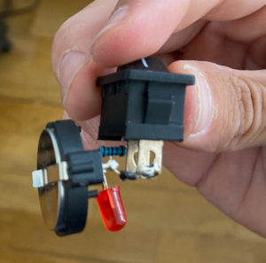
I rode my bike to the boat to start cutting away at the housing to see this in action. I was pretty confident I nailed it in one go, so I was optimistic when I made the cuts into the plastic. I set the switch into the housing and it slid in fairly well, and I have to say that was a satisfying feeling since the switch sat flush.
But! There was a quick and disappointing realization I had when trying to screw it back on.
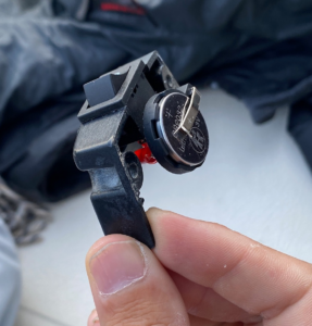
If you can’t tell what’s wrong, it’s the big honkin’ battery sticking out. It was not going to fit back on since the assembly needed to sit flush against the mount. Okay… well not the result I wanted, but I knew what I needed to fix at least!
Attempt #2
I knew I had to compact things, so I looked more into ideas around allowing more flexibility to where I could put the battery. I also texted with a few friends who had an idea to cut out more of the housing where the wires sat (the very first picture for reference… the back of it is hollow so this was a good idea!).
So, without further ado here was the second assembly attempt:
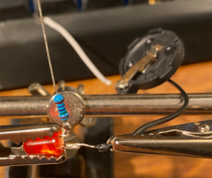
First thing I did was connect wires to the battery holder which would let me stuff it into the area I cut into the housing where it would not be in the way. Then I just wrapped up the other stuff as tight as I could, with some hot glue to hold things stable (remember that on the sea things go bump).
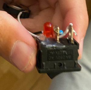
Not perfect, but it didn’t need to be! So then I just needed to wrap it all up in the housing and try to fit it again!
The results
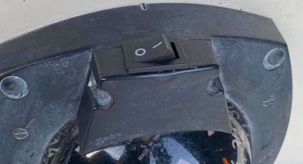
After my second attempt I was extremely happy with the resulting flushness and the overall appearance of how the switch was presented. But! How did it work? The whole point was not to just make a pretty switch, but to be able to see the numbers at night!

And let’s hit the switch and see how we did!

A smashing success!
Conclusion
This is the beauty of stringing together a few small components. Rather than spending a lot of money to replace something just because it was not usable at night, I was able to give it new life. I also have to say I do also enjoy tinkering with electronics. In total I estimate that if I paid for an ACTUALLY decent replacement that fit the specs of the previous mount, I would probably have spent about $100-$150 at least. But for only about $15 I don’t need to. A net savings of $85 in the best case replacement cost.
I would challenge most people to do similar before tossing something away. Granted there was no urgency here, so I could take the time, but this is often the case with things that break. It can take a few attempts to get things right, but the result when you do is more than just the functionality, you will also have some good experience that carries into other projects as well.
I guess I could have just bought a headlamp now that I think about it… but that is so much more boring.

